Er Diagram For Atm System Atm System Uml Diagrams
Class diagram for an atm system: step-by-step guide Srs atm Atm: dfd level 1
DFD for ATM system - GeeksforGeeks
Atm erd diagram Er diagram for atm Atm system uml diagrams
Object oriented software engg. uml : oose uml diagram
Atm process flow chartAtm creately entity erd What is an entity relationship diagram (erd)?Partial key representation in er diagram.
Er diagram for atm systemAtm machine drawing at getdrawings Dfd for atm systemErd diagram example – ermodelexample.com.
Use case diagram for atm system in uml
Atm system er diagramUml object diagram for atm Dfd atm geeksforgeeksAtm system dfd level project automated teller last go next.
Dfd for atm systemErd entity database atm represents conceptual reservation dbms ermodelexample explained Atm system uml diagramsAtm machine er diagram.

Erd entities cardinality relational construct key mca constraints
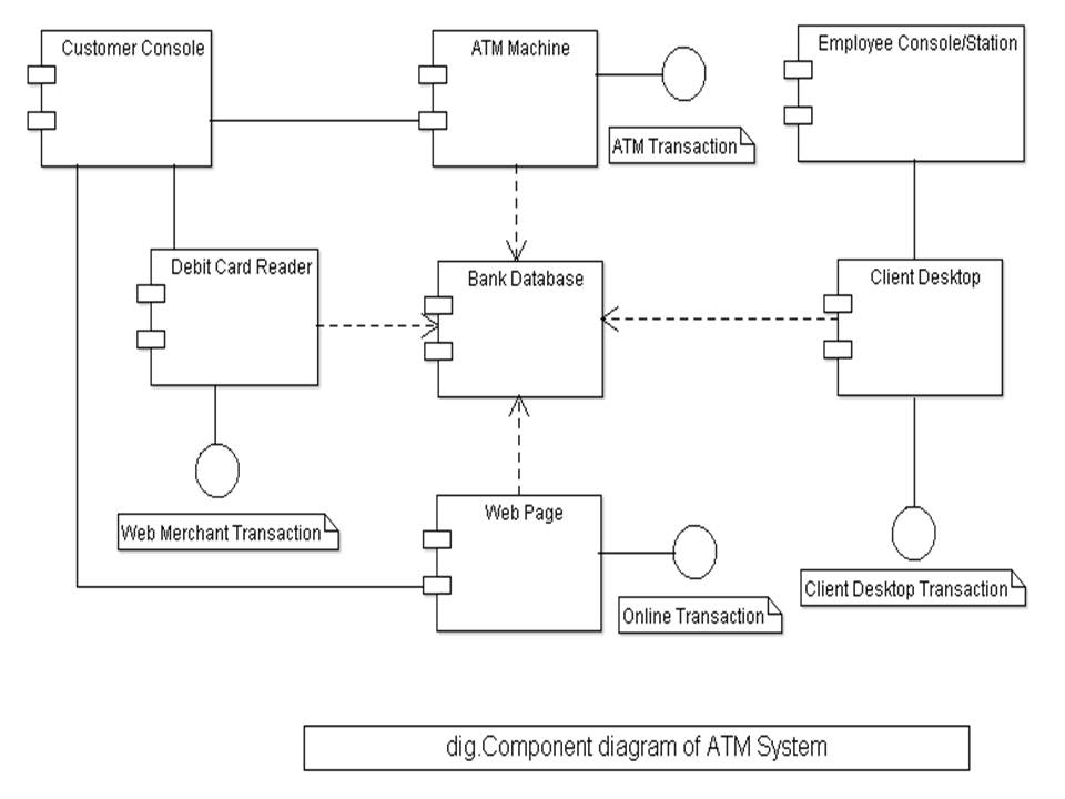
Diagram erd er entity relationship components conceptdraw software examples diagrams notation atm chen example symbols reference wordpress sample drawing systemAtm system uml diagram component diagrams Atm system er diagram20+ er diagram for atm system.
Dfd atm geeksforgeeksEr diagram of banking management system Circuit diagram of atm machineContoh dari basis data erdplus er diagram.

Component diagram for atm system
Er diagram for atm system20 er diagram for atm system carolestorm Machine atm er diagram software ppt powerpoint presentationClass diagram for atm management system.
Atm system er diagramDiagram uml class atm machine application diagrams case use object model software patterns teller oose oriented automatic programs notes after Class diagram for atm system in umlAtm system er diagram.

Atm system chen erd
Atm transaction component diagram .
.


